Function Characteristics:
●Flame retardant, non-pollution, it can be installed directly in the load center.
●Maintenance-free, easy to be installed, low operating costs.
●The enclosure can be of Good moisture resistance, transformer can be put into operation without pre-drying under 100% humidity in the normal operation.
●Low loss, light weight and small volume, low noise, good dissipation of heat, it can be 150% rated load operation under forced air cooling conditions.
●Equipped with a complete temperature protection control system to provide reliable protection for the safe operation of transformers.
●High reliability. The results of checking for the products that has been put into operation show that the reliability index has reached the international advanced level.
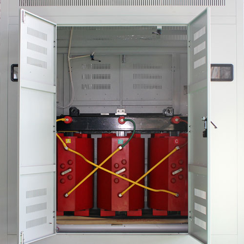
Structural Characteristics:
Foil Coil: Adopting the entire section of copper foil, together with the F-class turn insulation, low voltage winding is wound by the special low-voltage foil winding machine. The foil coil resolves problems such as large short-circuit stress, ampere turn unbalance, poor heat dissipation, existing the winding spiral angle and unsteady manual welding quality due to low voltage and large current coil. At the same time, the end of winding is treated with cast resin, solidification to make shape, moisture-proof and anti-fouling, the lead for copper bar is welded by argon arc welding automatically.
Temperature Control Device: the transformer adopts BWDK series of signal thermometer. The temperature components are embedded in the upper half of the low-voltage coil, can detect and display the temperature of separate phase coil automatically and continuously, also have the functions of over-temperature alarm and trip.
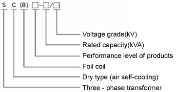
Model and Meaning
Technical Parameter for 6kV, 10kV& 30kVA-2500kVA With Off Circuit Dry Type Transformer
| (KVA)Rated capacity |
Voltage Combination |
Connection Group Symbol |
No-load Loss(W) |
Load Loss (W) |
No-load Current (%) |
Short-circuit Impedance(%) |
| High Voltage (KV) |
Tapping ranges of High Voltage |
Low Voltage(KV) |
130℃(B) (100℃) |
155℃(F) (120℃) |
180℃(H) (145℃) |
| 30 |
6
6.3
6.6
10
10.5
11 |
±2.5%
±5% |
0.4 |
Dyn11 Yyn0 |
190 |
670 |
710 |
760 |
2.0 |
4.0 |
| 50 |
270 |
940 |
1000 |
1070 |
2.0 |
| 80 |
370 |
1290 |
1380 |
1480 |
1.5 |
| 100 |
400 |
1480 |
1570 |
1690 |
1.5 |
| 125 |
470 |
1740 |
1850 |
1980 |
1.3 |
| 160 |
540 |
2000 |
2130 |
2280 |
1.3 |
| 200 |
±2X2.5%
±5% |
620 |
2370 |
2530 |
2710 |
1.1 |
| 250 |
720 |
2590 |
2760 |
2960 |
1.1 |
| 315 |
880 |
3270 |
3470 |
3730 |
1.0 |
| 400 |
980 |
3750 |
3990 |
4280 |
1.0 |
| 500 |
1150 |
4590 |
4880 |
5230 |
1.0 |
| 630 |
1340 |
5530 |
5880 |
6290 |
0.85 |
| 630 |
1300 |
5610 |
5960 |
6400 |
0.85 |
6.0 |
| 800 |
1520 |
6550 |
6960 |
7460 |
0.85 |
| 1000 |
1770 |
7650 |
8130 |
8760 |
0.85 |
| 1250 |
2090 |
9100 |
9690 |
10300 |
0.85 |
| 1600 |
2450 |
11000 |
11700 |
12500 |
0.85 |
| 2000 |
3050 |
13600 |
14400 |
15500 |
0.70 |
| 2500 |
3600 |
16100 |
17100 |
18400 |
0.70 |
| 1600 |
2450 |
1220 |
12900 |
13900 |
0.85 |
8.0 |
| 2000 |
3050 |
15000 |
15900 |
17100 |
0.70 |
| 2500 |
3600 |
17700 |
18800 |
20200 |
0.70 |
The load losses listed in the table are the values of the reference temperature for different insulation systems in parentheses; The load losses under other insulation system temperatures that are not included in the table should be according to their respective reference temperatures, the corresponding calculation is based on the"- 155 ℃ (F)" insulation system temperature data.
Notes: The Dimension and weight will be changed according to the requirements. These two data in the table will be subject to the factory documents.
Technical Parameter for 20kV & 50kVA-2500kVA With Off Circuit Dry Type Transformer
| (KVA)Rated capacity |
Voltage Combination |
Connection Group Symbol |
No-load Loss(W) |
Load Loss (W) |
No-load Current (%) |
Short-circuit Impedance(%) |
| High Voltage (KV) |
Tapping ranges of High Voltage |
Low Voltage(KV) |
130℃(B) (100℃) |
155℃(F) (120℃) |
180℃(H) (145℃) |
| 50 |
20
22
24 |
±2.5%
±5% |
0.4 |
Dyn11 Yyn0 |
340 |
1160 |
1230 |
1310 |
2.0 |
5.0 |
| 100 |
540 |
1870 |
1990 |
2130 |
1.8 |
| 160 |
670 |
2350 |
2470 |
3460 |
1.8 |
| 200 |
±2X2.5%
±5% |
730 |
2770 |
2940 |
3140 |
1.8 |
| 250 |
840 |
3220 |
3420 |
3660 |
1.8 |
| 315 |
970 |
3850 |
4080 |
4360 |
1.8 |
| 400 |
1150 |
4650 |
4840 |
5180 |
1.1 |
| 500 |
1350 |
5460 |
5790 |
6190 |
1.1 |
| 630 |
1530 |
6450 |
6840 |
7320 |
1.0 |
| 800 |
1750 |
7790 |
8260 |
8840 |
1.0 |
| 1000 |
2070 |
9220 |
9780 |
10400 |
0.85 |
| 1250 |
2380 |
10800 |
11500 |
12300 |
0.85 |
| 1600 |
2790 |
13000 |
13800 |
14800 |
0.85 |
| 2000 |
3240 |
15400 |
16300 |
17500 |
0.70 |
8.0 |
| 2500 |
3870 |
18200 |
19300 |
20700 |
0.70 |
| 2000 |
3240 |
16800 |
17800 |
19100 |
0.70 |
| 2500 |
3870 |
20000 |
21200 |
22700 |
0.70 |
Technical Parameter for 35kV & 50kVA-2500kVA With Off Circuit Dry Type Transformer
| (KVA)Rated capacity |
Voltage Combination |
Connection Group Symbol |
No-load Loss(W) |
Load Loss (W) |
No-load Current (%) |
Short-circuit Impedance(%) |
| High Voltage (KV) |
Tapping ranges of High Voltage |
Low Voltage(KV) |
130℃(B) (100℃) |
155℃(F) (120℃) |
180℃(H) (145℃) |
| 50 |
35
36
37
38.5 |
±2.5%
±5%
|
0.4 |
Dyn11 Yyn0 |
450 |
1340 |
1420 |
1520 |
2.3 |
6.0 |
| 100 |
630 |
1970 |
2090 |
2230 |
2.0 |
| 160 |
0.790 |
2650 |
2810 |
3000 |
1.5 |
| 200 |
±2X2.5%
±5% |
0.880 |
3130 |
3320 |
3550 |
1.5 |
| 250 |
0.990 |
3580 |
3800 |
4060 |
1.3 |
| 315 |
1170 |
4250 |
4510 |
4820 |
1.3 |
| 400 |
1370 |
5100 |
5410 |
5790 |
1.1 |
| 500 |
1520 |
6270 |
6650 |
7110 |
1.1 |
| 630 |
1860 |
7250 |
7690 |
8230 |
1.0 |
| 800 |
2160 |
8600 |
9120 |
9760 |
1.0 |
| 1000 |
2430 |
9860 |
10400 |
11100 |
0.75 |
| 1250 |
2830 |
12000 |
12700 |
13600 |
0.75 |
| 1600 |
3240 |
14600 |
15400 |
16500 |
0.75 |
| 2000 |
3820 |
17200 |
18200 |
19500 |
0.75 |
| 2500 |
4450 |
20600 |
21800 |
23300 |
0.75 |